The Foundation of CNC Technology
Before a tool ever touches raw material, a rigorous digital workflow must be executed. Computer Numerical Control (CNC) relies on precise mathematical coordinates to dictate machine movement, speed, and tooling changes.
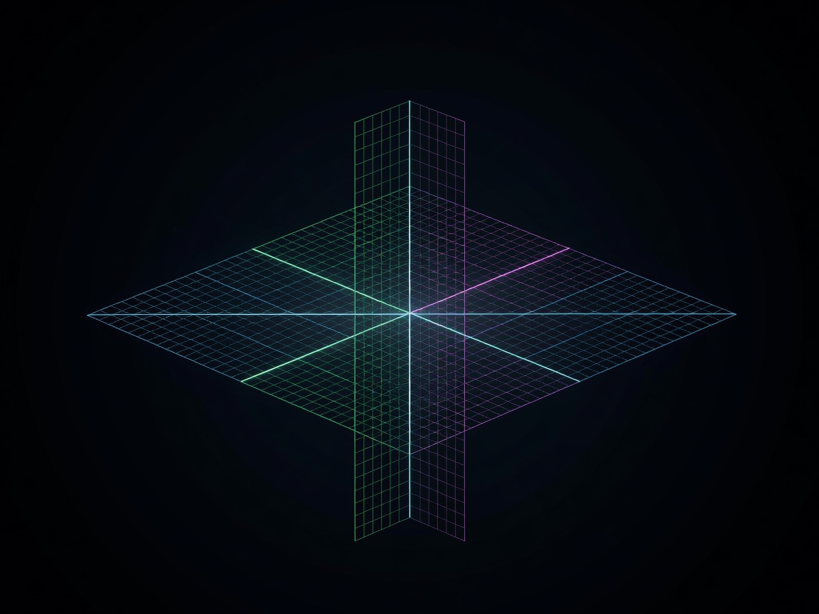
Coordinate Systems
All CNC machining is based on the Cartesian coordinate system (X, Y, Z). To command a machine, the controller must establish a known starting point, referred to as the machine zero or home position. From there, a Work Coordinate System (WCS) is established.
- G54 to G59: Standard work offsets that allow the programmer to set a localized zero point on the physical workpiece.
- Tool Length Compensation (G43): Adjusts the Z-axis coordinate to account for the physical length of the cutting tool mounted in the spindle.
The Anatomy of G-Code
G-Code (General or Geometric Code) is the standardized programming language for CNC machines. It directs the interpolators within the machine's control unit.
| Command | Description |
|---|---|
| G00 | Rapid Positioning (non-cutting movement) |
| G01 | Linear Interpolation (straight line cutting feed) |
| G02 / G03 | Circular Interpolation (clockwise / counter-clockwise) |
| M03 / M04 | Spindle On (clockwise / counter-clockwise) |
| M06 | Automatic Tool Change |
Machine Controllers
The controller is the brain of the CNC machine. While G-code is mostly standardized (EIA-274-D), different manufacturers implement proprietary cycles and macro capabilities. Common industrial control units include those manufactured by Fanuc, Haas Automation, and Siemens SINUMERIK systems. These controllers read blocks of code ahead of time (look-ahead) to calculate smooth acceleration and deceleration curves, preventing tool breakage and surface gouging.